4. Signifificance and Use
4.1 Transparent plastic materials, when used as windows or
enclosures, are subject to wiping and cleaning; hence the
maintenance of optical quality of a material after abrasion is
important. It is the purpose of this test method to provide a
means of estimating the resistance of such materials to this type
and degree of abrasion. 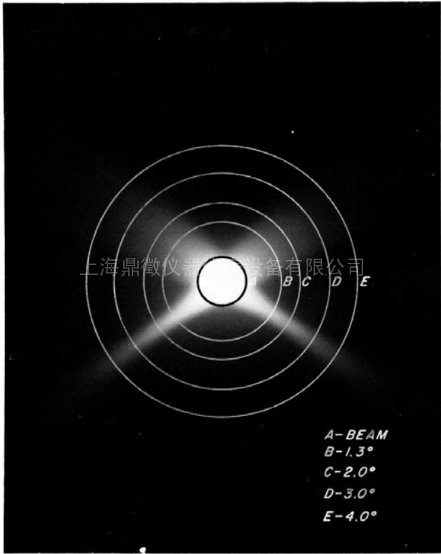 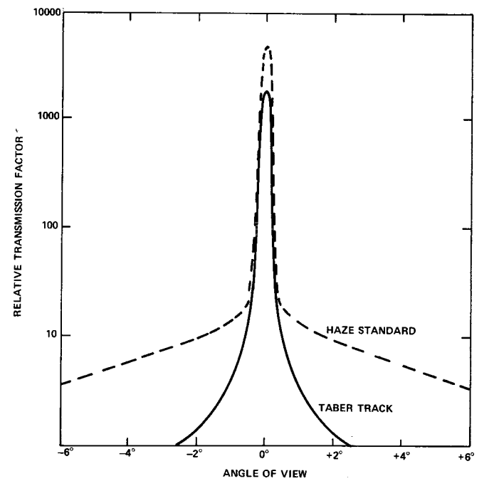
4.2 Although this test method does not provide fundamental
data, it is suitable for grading materials relative to this type of
abrasion in a manner which correlates with service.
4.3 Comparison of interlaboratory data or the specifification
of a “haze” value has no signifificance if the hazemeter
requirements given in 5.4 are not used. This is because light
diffused from the surface of a Taber track is scattered at a
narrow angle (Fig. 1 and Fig. 2) while light diffused internally
by a specimen is scattered at a wide angle. In many hazemeters,
when a diaphragm is inserted to limit the light beam to the
width of the abraded track, the specular beam at the exit port
becomes smaller. The dark annulus will then be greater than the
0.023 6 0.002 rad (1.3 6 0.1°) requirements of Test Method
D 1003. Since a large percentage of the narrow-angle forward
scattered light will not impinge on the sphere wall, “haze”
readings become smaller. For hazemeters that have not been
properly adjusted, the magnitude of this reduction is dependent
both on the integrating sphere diameter and the reduction of the
entrance beam.
4.4 For many materials, there may be a specifification that
requires the use of this test method, but with some procedural
modififications that take precedence when adhering to the
specifification. Therefore, it is advisable to refer to that material
specifification before using this test method. Table 1 of Classi-
fification System D 4000 lists the ASTM materials standards that
currently exist.
4.5 For some materials, abrasion tests utilizing the Taber
abraser may be subject to variation due to changes in the
abrasive characteristics of the wheel during testing.
4.5.1 Depending on abradant type and test specimen, the
wheel surface may change (that is, become clogged) due to the
pick up of coating or other materials from test specimens and
must be cleaned at frequent intervals.
4.5.2 The type of material being tested and the number of
test cycles being run is known to sometimes inflfluence the
temperature of the running surface of the wheel with an affect
on the fifinal haze measurement. To reduce any variability due to
this temperature effect, stabilize the wheels surface tempera
ture prior to performing actual measurements. This shall be
accomplished by conducting multiple refacings on an ST-11
refacing stone, followed by a test on the sample material to be
tested (with results to be discarded).
5. Apparatus
5.1 Abrader—The Taber abraser or its equivalent, consist
ing of the following elements:
5.1.1 A horizontal turntable platform; comprised of a rubber
pad, clamp plate, and nut to secure the specimen to the
turntable.
5.1.2 A motor capable of rotating the turntable platform at a
speed of either 72 6 2 r/min for 110v/60Hz or 60 6 2 r/min for
230v/50Hz.
5.1.3 A pair of pivoted arms, to which the abrasive wheels
and auxiliary masses (if used) would be attached; loads of 500
or 1000 gf on the wheels are obtained by use of changeable
weights.
NOTE 5—Without auxiliary masses or counterweights applied, each
arm will apply a load against the specimen of 250 gf per wheel (exclusive
of the mass of the wheel itself).
5.1.4 A vacuum suction system and vacuum pick-up nozzle
to remove debris and abrasive particles from the specimen
surface during testing. The height of the vacuum pick-up
nozzle shall be adjustable, and the nozzle openings shall be 11
mm [7⁄16 in.] in diameter.
NOTE 6—The nominal nozzle openings are 8 mm [5⁄16 in.] and can be
enlarged following the instructions shown in Appendix X2.
5.1.5 A counter to record the number of cycles (revolutions)
made by the turntable platform.
5.2 Refacing Stone—The fifine side of a ST-11 refacing stone
(or equivalent) shall be used for refacing the abrasive wheels.
It is important that the turntable platform runs true on the
abraser and that the refacing stone lies flflat on the turntable
platform.
5.3 Abrasive Wheels—The grade of wheel designated CS-
10F5 shall be used, and shall meet the following requirements
at the time of the test:
5.3.1 The wheel shall be 12.7 6 0.3 mm wide and have an
external diameter of 51.9 6 0.5 mm when new, and in no case
less than 44.4 mm, and
5.3.2 The wheel shall not be used after the date stamped on
it.
5.4 Hazemeter—An integrating sphere photoelectric pho
tometer, as described in Test Method D 1003, shall be used to
measure the light scattered by the abraded track. If haze
measurements are made with other devices or by other meth
ods, a correlation shall be established with the results obtained
with the apparatus and method described in Test Method
D 1003.
5.4.1 An aperture or diaphragm shall be centrally inserted in
the haze measuring apparatus to center the light beam on the
abraded track and limit it to a diameter of 7 6 1 mm [0.28 6
0.04 in.] at the specimen.
5.4.2 When the reduced light beam is unobstructed by a
specimen, its cross section at the exit port shall be approxi
mately circular, sharply defifined, uniformly bright, and concen
tric within the exit port, leaving an annulus of 0.023 6 0.002
rad (1.3 6 0.1°) subtended at the entrance port.
5.5 Specimen Holder—A suitable holder shall be used to
permit positioning the abraded specimen on the hazemeter so
that the light beam is centered in the abraded track and the
specimen is flflush at the measurement port.
6. Test Specimens
6.1 The test specimens shall be clean, transparent disks
approximately 100 mm in diameter or plates approximately
100 mm square, having both surfaces substantially plane and
parallel. They may be cut from sheets or molded in thicknesses
up to 12.7 mm [1⁄2 in.]. A 6.3-mm [1⁄4-in.] hole shall be
centrally drilled in each specimen. Three such specimens shall
be tested per sample, except for interlaboratory or specifification
tests when ten specimens shall be tested.
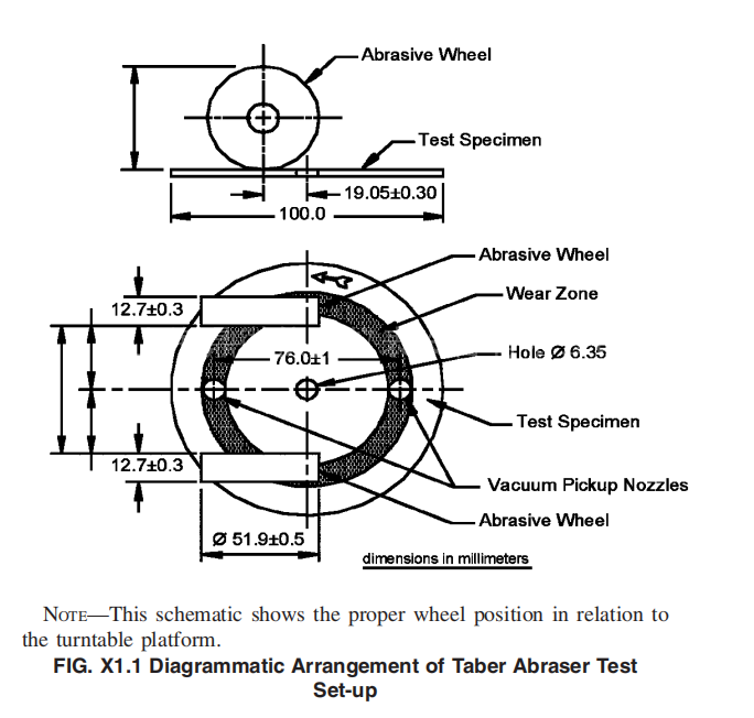
7. Calibration
7.1 Verify calibration of the Taber abraser as directed by the
equipment manufacturer (see Appendix X1).
8. Conditioning
8.1 Conditioning—Unless otherwise specifified, condition
the test specimens at 23 6 2°C [73.4 6 3.6°F] and 50 6 5 %
relative humidity for not less than 40 h prior to test in
accordance with Procedure A of Practice D 618. In cases of
disagreement, the tolerances shall be 61°C [61.8°F] and
62 % relative humidity.
8.2 Test Conditions—Conduct tests in the standard labora
tory atmosphere of 23 6 2°C [73.4 6 3.6°F] and 50 6 5 %
relative humidity, unless otherwise specifified. In cases of
disagreements, the tolerances shall be 61°C [61.8°F] and
62 % relative humidity.
9. Standardization of Abrading Wheels
9.1 To ensure that the abrading function of the wheels is
maintained at a constant level, prepare the abrading wheels
prior to each test.
9.1.1 Mount the wheels on their respective flflange holders,
taking care not to handle them by their abrasive surfaces.
9.1.2 Select the load to be used and affix it to the abraser. If
no load is specifified, use a load of 500 gf (per wheel).
9.1.3 Mount an ST-11 refacing stone (or equivalent) on the
turntable, fifine side up, and secure using the nut.
9.1.4 Lower the vacuum nozzle and adjust its height to
within 0.8 to 1.6 mm [1⁄32 to 1⁄16 in.] of the refacing stone. Set
the vacuum suction force to 100.
9.1.5 Lower the arms so the wheels contact the surface of
the ST-11 refacing stone.
9.2 Before abrading each specimen, reface the wheels for 25
cycles on the fifine side of the ST-11 refacing stone. After
refacing, use a soft bristle, anti-static brush to lightly brush the
wheel surfaces to remove any loose particulate matter before
abrading a specimen. (Warning—Do not touch the running
surface of the wheels after they are refaced. New wheels or
wheels trued using a diamond tool refacer, must fifirst be broken
in with 100 cycles on the fifine side of the ST-11 refacing stone
followed by a test on the material to be evaluated (results to be
discarded).)
NOTE 9—A brush found suitable for this purpose has been described as
follows: Having a width of two inches with tuft spacing of 0.25 inches. It
is a soft-fifiber, static-dissipative brush manufactured from an acrylic fifiber
(0.0015 inch fifilament diameter) that has been chemically bonded with a
layer of copper sulfifide to produce a resistance of 3–5 times 10-4 ohms per
centimetre.
NOTE 10—The fifine side of the ST-11 refacing stone has a limited life
and must be replaced after 10,000 cycles (approximately 400 refacings).
9.2.1 A thin fifin of wheel material will sometimes form on
the left hand edge of the wheel as the main body of the wheel
wears down. To remove, gently rub the edge of the wheel using
your fifinger. Avoid touching the running surface of the wheel.
9.2.2 The maximum allowed time between refacing and
testing shall not exceed two minutes.
10. Procedure
10.1 Before testing, remove any protective masking mate
rial from the specimen. If required, clean the specimen using a
practice recommended by the manufacturer. Handle test pieces
by their edges to prevent contamination of their surfaces.
10.2 Place the unabraded specimen in the hazemeter sample
holder with the side to be abraded facing the entrance port of
the integrating sphere. Measure the haze percentage (initial
haze) of the specimen at a minimum of four equally spaced
points in the unabraded area. The results shall be averaged for
each specimen.
NOTE 11—As an operational qualifification step for the instrumental
measurement of transmission haze, it is recommended to measure the haze
percentage value with no sample present and verify that the reading of the
hazemeter is 0. The sample holder must be removed during this measure
ment.
10.3 Mount the specimen on the abraser turntable platform
with the side to be abraded facing up. Secure using the clamp
plate and nut.
10.4 Select the load to be used and affix it to the abraser.
Lower the vacuum pick-up nozzle and adjust the height to
within 0.8 to 1.6 mm [1⁄32 to 1⁄16 in.] of the specimen surface.
Set the counter to zero and program the appropriate number of
cycles. Start the abraser and subject the specimen to abrasion
for a selected number of cycles. Use an abrasion of 100 cycles
with the 500 load, unless otherwise specifified.
remaining particulate. For those materials where IPA inflfluences
the surface characteristics, use deionized water or a cleaning
solution that is compatible with the sample.
10.6 Place the abraded specimen in the hazemeter sample
holder with the abraded track against the entrance port of the
integrating sphere (facing away from the light source). Mea
sure the haze percentage of the transmitted light that is diffused
by the abraded track (fifinal haze) on at least four equally spaced
intervals along the track. The results shall be averaged for each
specimen. The specimen holder shall be positioned so that no
portion of the light beam is within 1 mm of the inside or
outside edge of the track.
10.6.1 Percent haze, as defifined by Test Method D 1003, is
calculated as follows:
haze 5 [Td / Tt# 3 100 (1)
where:
Tt
= total transmittance
Td
= diffuse transmittance
NOTE 14—Subjective comparisons may be made by visually comparing
abraded specimens with a measured, abraded standard.
10.7 The initial haze percentage of the unabraded specimen
determined by 10.2 shall be subtracted from the fifinal haze
percentage of the abraded sample as measured by 10.6. The
difference represents the light scatter resulting from abrading
the specimen.
11. Interpretation of Results
11.1 The lower the percent haze difference, the more resis
tant the specimen is to abrasive damage.
12. Report
12.1 Report the following information:
12.1.1 Change in percentage of haze as calculated by 10.7,
12.1.2 Number of specimens tested,
12.1.3 Load and the number of cycles used, if other than
specifified in 10.4,
12.1.4 Wheel cleaning interval(s), if clogging is an issue,
12.1.5 Temperature stabilization details (in accordance with
4.5.2), if applicable,
12.1.6 Cleaning solution used, if applicable,
12.1.7 Rotational speed of turntable platform,
12.1.8 Plot of the percentage of light scattered versus cycles
abraded, if more than one number of cycles is used, and
12.1.9 Description of the integrating sphere photometer
including: sphere geometry; exit light beam diameter with and
without the diaphragm inserted; and location of the diaphragm
in the light beam. Alternatively, report the make and model of
the hazemeter used.
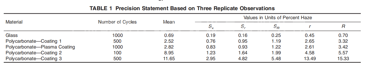
13. Precision and Bias
13.1 Table 1 is based on a round robin conducted in 2004,
involving fifive materials tested by fifive laboratories. Each lab
made six (6) determinations for each material and cycle
combination. It should be noted that the test procedure used for
the round robin involved higher reface cycles, and no consid
eration was given to the useful life of the ST-11 refacing stone.
13.1.1 In Table 1 for the materials indicated:
Sr = pooled within-laboratories standard deviation of the
mean for three or ten specimens,
SR = total among-laboratories standard deviation of the mean
for three or ten specimens,
r = 2.83 Sr (see 13.2), and
R = 2.83 SR (see 13.3).
Other materials may give somewhat different results.
13.2 Repeatability—In comparing two averages for the
same material, obtained by the same operator using the same
equipment on the same day, the average should be judged not
equivalent if they differ by more than the r value for that
material and condition.
13.3 Reproducibility—In comparing two averages for the
same material, obtained by different operators using different
equipment, the averages should be judged not equivalent if
they differ by more than the R value for that material and
condition.
13.4 The judgments in accordance with 13.2 and
|