如果有技术问题请联系 上海鼎振仪器设备有限公司
This document is to be considered as a whole, the parts of which shall not be separated. "Seul le texte français fait foi, les traductions n'étant faites que pour en faciliter l'emploi". "The French text alone is valid. The translations are provided to assist the reader in understanding the standards". © RENAULT 2002. No duplication permitted without the consent of the issuing department. No circulation permitted without the consent of RENAULT.
DATE OF ISSUE May 1999 - - - This issue originates from Draft NC 1999 0219 / - - A REVISIONS October 2001 - - A Complete revision, the test piece or part sections are from now on dealt with in draft Standards 2001 0527 and 2001 0528. This issue originates from Draft NC 2001 0535 / - - June 2002 - - B Paragraphs 3., 4., 5., 6., 7. and annexes 2. and 2.2. modified. This issue originates from Draft NC 2002 0242 / - - -.
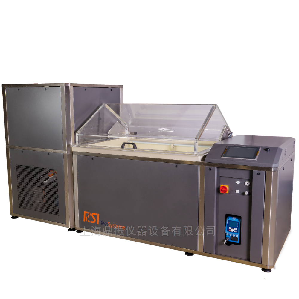
1. SCOPE AND FIELD OF APPLICATION This test method is intended to describe a cycle of the cyclic corrosion test 1 (Essai de Corrosion Cyclique 1: ECC1) on the associated equipment and the verifications which are necessary to make sure that the test is in conformity. This method may be applied to laboratory test pieces, to parts, or samples of vehicle parts. 2. PRINCIPLE The test pieces and/or parts are placed in an automatic corrosion chamber where they are exposed to a succession of attacks in controlled atmospheres, which simulate natural contamination by chloride ions, exposure to hot and humid atmosphere, and hot and dry atmosphere conditions. 3. APPARATUS AND REAGENTS 3.1. AUTOMATIC CORROSION CHAMBER This chamber shall make it possible to program the phases described below and to alternate them: NOTE: All these phases shall be performed at a controlled temperature of 35 °C ± 0,8 °C; their durations shall be programmable. 3.1.1. Contamination phase with spraying of saline solution The machine design shall make it possible to adjust the spray homogeneity and to obtain a rain quantity of 5 ml/h ± 1 ml/h at all points of the vat with the chamber empty or loaded. The pressure is between 0,7 bar and 1,6 bar. Moreover, in order to check that the salt spray phase has effectively taken place, the chamber shall be fitted with a system used to check the flow rate and total consumption of the saline solution. 3.1.2. Controlled humidity and drying phase The hygrometry shall be variable between 20 % and 95 % relative humidity with a constant air flow rate according to the profile defined in annex 1. The accepted tolerance is ± 3 % relative humidity, except for the 20 % relative humidity point where the accepted tolerance is ± 5 %. 3.1.3. Flushing phase This air flushing phase shall make it possible to eliminate the spray present in the chamber at the end of the saline solution spraying phase. 3.1.4. Wall rinsing phase This phase consisting in rinsing the chamber walls with de-mineralised water makes it possible to eliminate the salts deposited during the saline solution spraying phase and thus prevents the accumulation and therefore the concentration of salts during the cycles, which has an influence on the relative humidity profile. This is done with a rinsing pipe with nozzles located on the circumference of the vat. No spraying of de-mineralised water on the parts or test pieces is allowed.
3.1.5. Chamber environment - This chamber shall be continuously connected to a saline solution tank. Use of a vat of limited capacity is recommended (to avoid solution variations: pH, Cl%). The vat shall be designed in such a way that it can be easily cleaned. Improper cleaning entails high flow drops, and therefore has an influence on the final quality of the test. This vat shall be made from a material which does not influence the pH (e.g. PVC), and shall be opaque to prevent bacteria and algae development during the test, which entails a degradation of the saline solution. - If the saline solution is prepared in the vat, the latter shall be fitted with a shaker which does not react to the saline solution (example: stainless steel shaker covered with a plastic sheath). The outlet of the vat shall be fitted with a filter to prevent any possible contamination of the circuit and therefore avoid the risk of blocking the sprayers. - The air entering the machine shall be de-oiled and filtered beforehand to avoid the presence of particles. This air has the following qualification: . Filtered dry air free of water, oil, . metallic or organic particles, impurities less than 0.2 mg/m 2 and diameter less than 5 µm. - The water supply to the air humidifier and humidifier shall be de-ionised and have a minimum resistivity of 200 000 Ohms. 3.2. HOLDERS The test piece holders shall be entirely made from a material which is incorruptible under the test conditions (for example, PVC) and shall make it possible to incline the test pieces an/or parts by 20 ± 5° with respect to the vertical. They shall be designed so as to avoid water retention areas. Moreover, it is very important that these holders be made so as not to interfere with the air flow in the chamber; therefore, it is necessary that all the PVC parts are hollowed to the maximum. Any streaming down the holders (for example, emanating from the water retention on the solution and air feed pipes, the wall rinsing, etc.) shall be avoided. The test pieces shall be positioned on a single level (for 9 cm x 19 cm test pieces) and be at a sufficient height to let the air flow in the chamber. NOTE: it is important for the quality of the test not to overload the chamber (identical profile relating to the relative humidity and volume of saline solution received by each test piece). Example: maximum 110 samples 9 cm x 19 cm for a vat capacity of 1 200 litres. 3.3. SODIUM CHLORIDE In the anhydrous state, the sodium chloride shall not contain more than 0,2 % of total impurities and more than 0,1 % of sodium iodide. 3.4. PH-METER (minimum accuracy 0,1 pH). 3.5. SULPHURIC ACID 0,5 mol/l (1 N). 4. SOLUTION PREPARATION It is preferable to prepare a new solution before each test, and not prepare more than 50 litres at a time for each chamber to avoid any changes in it over time. NOTE: For chambers, the volume of which is greater than 3 m 3 , the volume of saline solution to be prepared is left to the judgement of the users. The solution which is sprayed during this test is a 1 % Na Cl, pH4 solution. The solution is prepared before each test according to the following steps: - prepare the desired quantity of de-mineralised water (resistivity greater than 200 000 Ohms), - start the paddle, - add the quantity of salt which is calculated; the final solution is 1 ± 0,05 % NaCl (10 ± 0,5 g/l), - when the salt has dissolved, wait for 4 hours minimum, then adjust the pH of the solution to 4,0 ± 0,2 with sulphuric acid 1 N. To validate the salt concentration of the solution, the density is measured and recorded whenever the solution is prepared. It shall be between 1.0065 and 1.0075 (at 25 °C). The solution thus prepared is ready for the test. 5. PERIODIC VERIFICATIONS Annex No 2 presents the machine verification operations that must be performed. These verifications shall be performed every 12 weeks. Annexes 2.1 and 2.2 relate to the measured fallen rain quantity in a chamber of around 1 200 dm 3 . For a chamber with different dimensions, adapt the number of test points (manifolds). NOTE: For chambers, the volume of which is greater than 3 m 3 , the periodicity of the checks is left to the judgement of the users.
6. CYCLE DEFINITION A cycle lasts 24 hours. It is defined by the following phases: One ECC1 cycle ↓ Contamination NaCl 1 %, pH 4 35 °C during 0 H 30 |
↓ ↓ Wall rinsing 35 °C during 0 H 05 |
↓ ↓ Forced drying 35 °C - 20 % RH - during 1 H 40 |
↓ Drying 35 °C - 55 % RH - during 1 H 35 |
↓ ← ← Humidity 35 °C - 90 % RH - during 1 H 20 |
↓ ↑ Drying 35 °C - 55 % RH - during 2 H 40 |
↓ → → ↑
↓
After a prolonged stoppage of the chamber (greater than one day), perform a stabilisation phase lasting a minimum of 1 hour at 35 °C and 60 % relative humidity. Annex 1 presents the cycle profile with the chamber unloaded. Notes: - in the event of breakdown, rinse the parts with de-mineralised water and leave the chamber open, - the opening of the chamber during the test (to take the parts in and out of the chamber) shall be done during the phase with 55 % relative humidity which precedes the salt spray phase.
7. CORROSION TESTS PERFORMED All the items (definition, preparation, and position of the test pieces, aggressiveness check, end of test, results interpretation and test report) relative to corrosion tests based on the ECC1 cycle are defined in the following standards:
APPLICATION | STANDARD | Full skin on uncoated or painted pre-coated steel (single layer or complete scheme) | 02-00-005 | Non painted aluminium / coated or non coated steel assembly | 02-00-006 |
8. INSPECTION REPORT The inspection report shall include: - the heading "inspection report", - the document identification number, - the reference of this test method, - the references of the automatic chamber used, - the date of verification, - the characteristics during verification: . the air pressure during the spray phase, . the instantaneous flow-rate (if the chamber allows this), - the verification curves and results: . the Temperature/Humidity curves, . the recorded pluviometry relative to the verifications (see example of test sheet in annex 2.2.), - the evaluation considering the acceptance conditions. 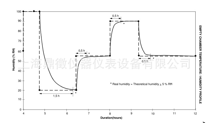
CHAMBER CHECK 1. CHECKING THE SPRAY PHASE: PLUVIOMETRY - The pluviometry shall be checked with the solution defined in § "Solution preparation". - Clean, dry, and weigh (to within ± 10 -2 g) the manifolds (test pieces 50 ml + funnels ∅ 100 mm). - Place the manifolds at the bottom of the chamber distributed so as to be able to evaluate the homogeneity of the fallen rain quantity (see example in annex 2.1.). - Condition the chamber during 1 hour minimum at 35 °C, then launch the spray mode during 30 minutes. - Immediately after the end of the spray mode (without a flush phase 3.1.3. or rinsing phase 3.1.4.), dry the outside of the manifolds, then weigh them. - Record the difference in weight with respect to the initial weight for each manifold, and convert it into ml/h. - Set the pressure, the flow rate, and the orientation of the sprayers in order to obtain a pluviometry of (5 ± 1) ml/h (i.e. between 2 and 3 g of condensates for 30-minute spraying) in all the manifolds. 2. VERIFICATION OF TEMPERATURE AND HUMIDITY PHASES - This is done using temperature and humidity measuring devices (examples: PT100 probes, hygrometer, etc.), placed at the centre of the chamber. - The following points are to be checked: 35 °C and 20 % RH during 4 hours, 35 °C and 40 % RH during 3 hours, 35 °C and 50 % RH during 3 hours, 35 °C and 60 % RH during 3 hours, 35 °C and 80 % RH during 3 hours, 35 °C and 90 % RH during 3 hours, 35 °C and 95 % RH during 3 hours. i.e. a total duration of 22 hours. - After 2-hour stabilisation and during an interval of half an hour: . the temperature shall be equal to 35 °C ± 1 °C, . the relative humidity shall be ± 3 % RH of the demanded set-point, except for the 20 % RH (± 5 % RH) point.
FALLEN RAIN QUANTITY MEASUREMENTS FOR A 1200 dm 3 CHAMBER approx. Example of a situation with manifolds inside an automatic corrosion chamber of 1200 dm 3 approx. 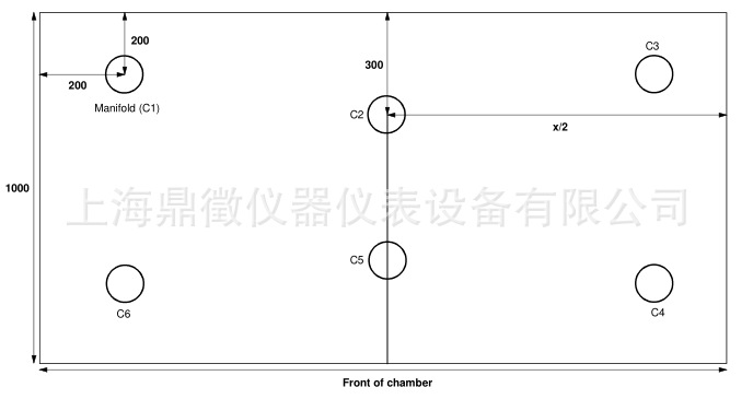
|